Hard-wired duty-cycle counter
18 September 2020This is an experimental circuit that uses
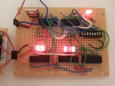
SN74HC161N ripple counters and CD74HC85 binary magnitude comparators to control the duty-cycle of a pulse wave derived from an external clock, and is intended as a try-out of the parts both of which are from Texas Instruments.
The duty cycle is configured via DIP switches which specify the duration in clock deltas of the “on” pulse part of the wave, and the internal counter state has been exposed via LEDs in order to clearly show what is happening.
This circuit was intended as the first stage of a hard-wired reimplementation of the control sub-system used in my solid-state AC control board.

Because of lack of space only the switch-off threshold is configurable via DIP switches and the total pulse wave length is fixed at 254 clock deltas. In practice this circuit amounted to trying out the magnitude comparator chips, a process that was made less than straight-forward by problems almost universally traced back to floating pins.
Magnitude comparison
One thing that caught my attention out is how the Texas InstrumentsCD74HC85 does comparison, and unlike identity comparators it has a weighting system that decided whether non-matching inputs are considered higher or lower.
The truth table is partially reproduced below, covering the single-chip case rather than multiple chips in a cascase arrangement.
| Comparison inputs | Outputs signals | |||||
A3, B3 |
A2, B2 |
A1, B1 |
A0, B0 |
A > B |
A < B |
A = B |
A3 > B3 |
X |
X |
X |
H |
L |
L |
A3 < B3 |
X |
X |
X |
L |
H |
L |
A3 = B3 |
A2 > B2 |
X |
X |
H |
L |
L |
A3 = B3 |
A2 < B2 |
X |
X |
L |
H |
L |
A3 = B3 |
A2 = B2 |
A1 < B1 |
X |
H |
L |
L |
A3 = B3 |
A2 = B2 |
A1 > B1 |
X |
L |
H |
L |
A3 = B3 |
A2 = B2 |
A1 = A1 |
X |
H |
L |
H |
A3 = B3 |
B2 = B2 |
A1 = A1 |
A0 > B0 |
L |
H |
L |
A3 = B3 |
B2 = B2 |
A1 = A1 |
A0 < B0 |
H |
L |
L |
A3 = B3 |
B2 = B2 |
A1 = A1 |
A0 = B0 |
L |
L |
H |
List of components
Even though I have a custom-written stock tracking program I tend to look back at past website articles I have written whenever I am trying to remember the identity of components I have forgotten, so these days I almost always include table of components and the one for this circuit is presented below. In the past I have sometimes also included pricing and vendor information although for the latter I tend to only include it when I source from somewhere other than Farnell. For this circuit many of the components were old stock, and this time round pretty much every single one selected in the speccing process had a story behind it.
| Component | Manufacturer | Part number |
| 5v voltage regulator | Texas Instruments | LM1085IT-5.0/NOPB |
| Phenolic prototyping board | Multicomp | MC01010 |
| 4-bit binary counter | Texas Instruments | SN74HC161N |
| 4-bit magnitude comparator | CD74HC85 |
|
| 8-channel SPDT switch | Multicomp | MCTIIR-08-T |
| Red LED | Kingbright | L-113IDT |
| 390Ω resistor | TE Connectivity | CFR25J390R |
- Prototyping board
- The prototyping board was the last in the pack which according to the faded label was ordered back in 2017 which brings with it a small amount of nostalgia. Think this stock lasted so long because after a burst of mostly time-keeping orientated circuits in December 2018 and January 2018 I preferred perf-board over this chip-orientated prototyping board.
- Binary counter
- I had not intended to use my old stock of Texas Instruments
SN74HC161N4-bit binary counters but the ones I was planning on using had no proper support for cascading. It was either use the old stock or wait until next week to do the project. - Voltage regulator
- Adding to the above the Texas Instruments
LM1085ITwas one that Farnell accidently shipped to me instead of theLM2904I ordered but after some messing around due to swapped pinning compared with what I was expecting I felt this oversight was not worth complaining about. - SPDT switch
- I had not intended to source a tri-state switch that includes a floating state but the
MCTIIR-08-Tjust happened to be the cheapest SPDT array I could find. - Resistors & LEDs
- Back in 2017 I was getting through a lot of LEDs so I bought a bulk stock of them, together with an even bigger stock of protective 390Ω resisitors. It will be a long time before either is exhausted.
De-soldering and re-soldering
A repair job I have done quite a few times is replacing the buttons one my Logitech M750 trackballs, most recently because I found the C&K ComponentsZMCJF7P0T0 tactile switches a bit too stiff and reverted back to some Omron D2FC-F-7N units of dubious quality obtained from E-Bay.
De-soldering the old switch is basically 95% of the effort and have usually ended up destroying the switch in the process, which also makes me wonder how close I come to damaging the trackball's PCB itself, so I gave in and decided to invest in a de-soldering station.
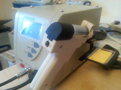
These are basically a combination of a soldering iron and a solder pump.
Originally I considered getting the Hakko FR-301 but at €250-300 I thought it was overpriced.
I eventually came across the Duratool D00672 which is a rebadged ZD-915 that goes for €100. There were even cheaper options out there but I wanted one that had settable temperature control.

It is a bit noisy and probably not built for heavy use, but so far it has been a great improvement over desoldering braid and a manual solder pump. For this circuit I ended up desoldering and resoldering several wires much more than I should have, but having the desoldering station takes the choir out of the former.