5-volt Buck converter
30 August 2020The circuit presented here is an experimental one using an ON Semiconductor
LM2576T-005G switching regulator to obtain 5-volt regulated DC power via a Buck step-down circuit from an unregulated DC source of upto 40 volts. The regulator chip itself does the switching control so the circuit itself just provides passive components required for the electrical properties — this project for me is intended as a gentle return to messing around with electronics.
This is a side-step from my recent forays into AC power relay control as one thing that has come up is converting 240-volt AC into 5-volt DC so that the control circuit does not need a separate power supply. While this DC-to-DC conversion circuit is not much use in terms of getting from 240-volt AC to regulated 5-volt DC I felt it was a mini-project worth trying out as a first step into switched mode power supply
Circuit design
The circuit is more or less a direct copy of the one given in the data-sheet for a typical application and the schematic is shown below. I suspect the 100μF by-pass capacitor on the left-hand side could have been omitted but with so few components needed in the first place skimping would not really be worth the potential trouble. Although a1N5822 schottky diode is suggested by the data-sheet I think any fast-recovery diode (‘recovery’ is how long before it blocks reverse current) will do.

I heard from some Youtube videos that this sort of circuit should have a toroidal inductor but instead I used a choke that although had the same inductance is intended for a different task. Guessing that chokes have a different frequency response and lower current rating, which might cause issues with how quickly the circuit can respond to changing loads, but from basic testing with a static load it seemed to work fine. I do not currently have the equipment at hand to prove otherwise. The list of components, complete with part numbers, is below:
| Part name | Manufacturer | Part number | Cost |
| Buck regulator | ON Semiconductor | LM2576T-005G |
€1.58 |
| Schottky rectifier diode | 1N5822 |
€0.36 | |
| 100μF 25V capacitor | Multicomp | MCGPR25V107M6.3X11 |
€0.06 |
| 1000μF 10V capacitor | MCKSK010M102G13S |
€0.13 | |
| 100μH choke | Bourns | 5800-101-RC |
€1.32 |
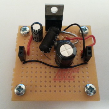
Circuit soldering
I am unsure which brand of perf-board it was since I have ordered in many different ones of this size, but since in more recent times I have preferred the slightly bigger 47x72mmMC01007, this may well be the last of the former size I will use for a project.
During assembly several issues came up but dealing with these is half the fun of doing electronics, and these are summarised in the list below.
- Regulator pins
- The regulator is not intended for prototyping board, having a highly inconvenient pin pitch of 1.7mm, so I ended up bending the pins quite a lot to fit the device onto the perf-board. I doubt the casing that has staggered pins would have been any better due to the awkward pin pitch, and as a result I suspect this component is not intended for use on prototyping board.
- Diode wire thickness
- The
1N5822schottky diode has leads that are too thick to go through the perf-board holes so I instead had to solder it across pins 2 and 5 on the top side of the board. Although I did have some other lower power-rated diodes that would have fitted but since they were not immediately to hand I did not feel like going looking for them. - Miswiring
- Being a long time since I last used perf-board I did mis-wire some connections, but I noticed and corrected these before I finished the circuit. In hindsight I should have put the inductor in the bottom half of the board rather than having it overlap the diode.
Switched vs. Linear regulator
Although switched power supplies are more efficent in most circumstances than linear regulators, I could not find much useful information on when a linear regulator would actually be preferable.The main one seems to be radio-frequency circuits due to the noise created by the switching process, but it seems in most other circuits this would not be an issue.Linear regulators are significantly cheaper and require less space, but the difference is managable — a significant portion of both is down to having an inductor rated in amperes rather than the milli-amps that most circuits use. A common rule-of-thumb seems to be that cost favours linear regulation below 10 watts but I have not seen any proper backing up of this threshold. One factor is powering of the switching controller itself and I note that theLM2576T-005G does have an internal 3.1-volt regulator, which presumably is itself a linear regulator. The whole Buck switching circuit consumes 7-8mA for itself so for something like my LCD-based timer which consumes a total 3.58mA when idle, a linear regulator is actually more efficent but I suspect this is an outlier. For now I can only guess that for maximum power cell life linear regulators are the best option below 25mW, but with some tuning and the right low-dropout regulator it could be as high as 100-200mW.