Power relay switch, 2nd gen.
12 August 2020One issue with my previous relay switch is that it was not able to switch the voltages I designed it for in the first place, so I decided to design a new one that had a much higher power rating. At the same time I decided to make it self-powered via the AC supply rather than relying on a separate DC power supply for the circuitry. Although in the end I decided not to build the circuit I had done all the design work short of sending the PCB files for fabrication I did not want the back-story to go to waste.
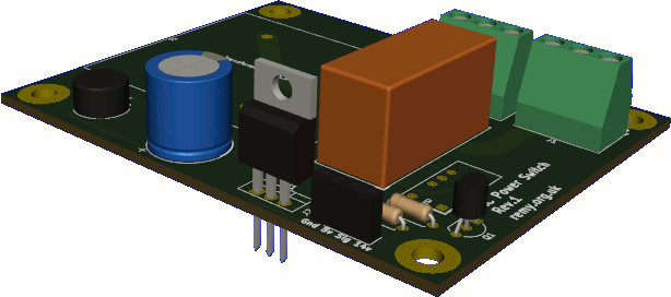
Circuit design
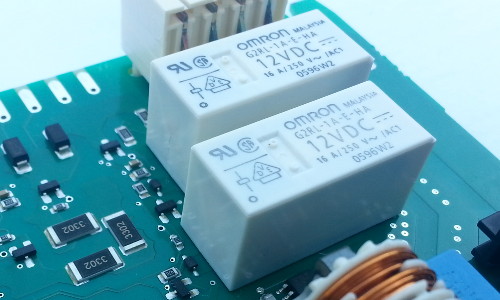
The circuit is based around an OmronG2RL-1A-E-HA power relay that I scavenged from a dish-washer control board, which given its 4-kilowatt power rating I suspect switched the heating coil.
It has a must operate voltage which is 70% of the maximum voltage which works out at 8.4 volts, although once activated for at least 100ms a lower holding voltage of 50% maximum is all that is needed to maintain the on state.
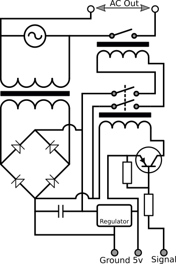
I felt there was no point having a 12-volt regulator so instead the coil is powered directly from the bridge rectifier, with the smoothing capacitor for the latter chosen so that the ripples are kept above 8.4 volts.
The coil power connection is itself switched using a Kemet EC2-5NU signalling relay which I used on my previous switch circuit, which as shown on the schematic below is in turn activated using a PNP transistor.
The circuit is intended to interface with and supply power to a separate control board, the latter of which uses the active-low signal line to control the nested power relays.
Ripple smoothing
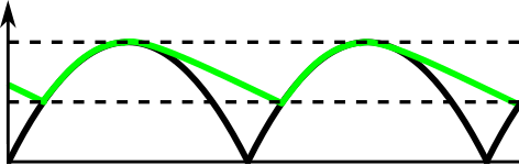
The raw output from a bridge rectifier is a varying DC voltage that periodically drops down to zero, so a capacitor is used to smooth the wave-form into something more consistent as shown in the image below. This variation in the voltage is known as the ripple voltage and is indicted by the two parallel dashed lines, and the larger the smoothing capacitor is the smaller the variation. Note that the ripple voltage is exaggerated in the image for illustrative purposes.
The ripple voltage Vripple is given by the equation below where I is the load current in amperes, f is the input AC frequency which is 50Hz in Europe, and C is the capacitance of the smoothing capacitor in Farads. Typically this smoothed voltage is used as input to a regulator so the capacitance C is chosen so that the voltage does not at any point fall below the regulator's drop-out voltage, which means using an estimate of the peak circuit current draw.
| Vripple = | I |
| 2 * f * C |
Half-wave rectifiers don't have the coefficent of 2 but some sources I have come across don't make it clear whether they are talking about half-wave or full-wave. Rearranging the equation for current gives:
I = 2 * f * C * Vripple
..and for capacitance:
| C = | I |
| 2 * f * V ripple |
Components
Although the circuit itself was never built most of the components I specified for the PCB I already had in stock or decided to order in anyway and these are listed in the table below. The order codes are for Farnell UK which for better or worse is still my go-to vendor for electronic components.
| Item | Manufacturer | Part number | Order code |
| Transformer (230v to 15v) | Myrra | 44268 |
1689089 |
| 5v LDO voltage regulator | Texas Instruments | LM2940CT-5.0/NOPB |
3122071 |
| Bridge rectifier | Multicomp | W005G |
2675426 |
| 3,300μF capacitor | MCKSK025M332I25S |
1902895 | |
| 2kΩ resistor | MF25 2K |
9341480 | |
| 10kΩ resistor | MF25 10K |
9341110 | |
| DPDT Signal Relay | Kemet | EC2-5NU |
2360823 |
| Power Relay | Omron | G2RL-1A-E-HA |
n/a |
| PNP Transistor | ON Semiconductor | BC556BTF |
2453802 |