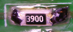
SMD resistor array
04 November 2017I finally decided to give reflow soldering of SMDs (Surface Mounted Devices), in this case a small board that is an array of eight 390Ω resistors. This resistor array was partly driven by an early annoyance of having to have banks of protective resistors for LEDs, but the main motive was having some low-cost training boards for first attempts at SMD reflowing, and at around 60¢ each I did not really see much down-side. I held off a long time because most solder paste is both pricey and has a limited shelf-life, but in the end I got some cheap solder paste — Mechanic XG-Z40, which was clearly a Chinese brand — I got off E-bay.
My original plan was to use a shrink-wrap hot air gun I had seen favourable reviews of, but from some quick tests with solder wire I was not convinced it was hot enough, so in the end opted for hot-plate reflowing instead. Neither really offered much in terms of temperature control, but at least with hot-plate reflow there would not be the problem of components being blown away. This first attempt at SMD reflow was actually two attempts one after the other, but I only took pictures during the second one.
Putting the paste down
The solder paste came in a syringe which I got a few needle ends for, but it did not really help — it came out in hard to manage blobs, and using a second unattached needle to work the blobs around did not really help. Advice I read is to use toothpicks but I doubt the real problem is the solder paste. Suppose I was asking for trouble, but I did not want to use the expensve stuff first time round. For the second board I was somewhat generous and varied with the amount of solder paste than I was for the first, because I wanted to see how much I could get away with using.
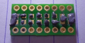
In hindsight I probably should have just put two horizontal strips of solder paste down, one across the upper pads and one across the lower pads — this seems the done thing with SMD microprocessors, and is just about the only non-fiddly way to apply this brand of paste. Any bridging between capacitors is easier to see & sort out than bridging across them.
Putting on the components
Despite my expectations, I found resistor placement to be easier without a microscope — most likely due to the angle of view it was messing up my eye-hand coordination, and what really mattered was good lighting rather than magnification. More importantly is having a decent pair of fine-nosed tweezers, my choice being curve-tipped ones that allow you to rest the side of your hand on the bench. Component placement is actually very quick, only taking maybe 2-3 minutes.Doing the cooking
Because of the small size of the PCB, I decided not to bother with a steel plate to spread out the heat, and put the PBC directly on the hob. I think for best results the hot-plate should be used from cold and that setting 3 or 4 (i.e. medium) should be used, but this needs further investigation and I have yet to check what the actual hot-plate temperatures are. Nothing seems to happen for best part of a minute, then suddenly you see the paste leech out flux and then shrink into smaller blobs of silvery solder, pulling the resistors into place.
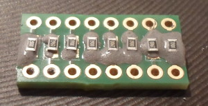
The solder paste had started to bubble a bit for the second attempt, which was a bit after the picture above was taken, which I put down to higher temperatures and the generally larger amounts of solder paste. In all ironies the far-right resistor, which is buried in solder paste, would actually come out alright.
The outcome
The finished reflow looks very different to how the board appears before heating, and at first glance it looks like all the resistors ended up much the same — closer examination shows otherwise. The first attempt had one or two resistors that were far from flat, but when checked all were within 1Ω of the expected resistance. The second attempt had one short-circuited resistor, which was the second-from-right — I was sort of half-expecting faults this time round, but I considered the far-left and far-right ones to more likley have problems.
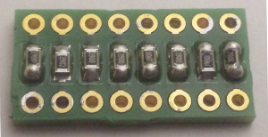
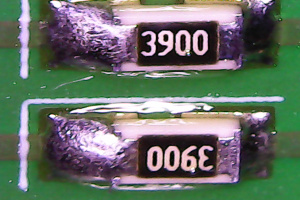
The best joints are the upper part of the second-from-left resistor, and the lower part of the third-from-left resistor. The lower part of the second-from-left resistor actually looks a bit deficent in solder, and almost all the other joints are ugly blobs. The second- and third-from-left resistors are shown under magnification below — stupidly the button for taking pictures on the microscope is the type that clicks, so getting a non-blurred picture is difficult:
Rework
Just to see what would happen I decided to try a bit of rework, mainly in an attempt to correct the shorted-out resistor. Reworking consisted of putting down a load of liquid flux (Edsyn FL911, Farnell 2576913) and using a soldering station to remelt the solder. My understanding is that solder flows towards heat sources, and in the process separate the solder bridge that is causing the short-circuit. The reworked resistor under magnification is shown below. Normally remelting solder is asking for all sorts of trouble, but the presence of flux does wonders — I could see the solder and flux flowing in opposite directions, and it successfully cleared the short-circuit.
I think the resistor sustained some damage in the process, as the metal bands on the top look like they have been pulled back, but checking with a multi-meter showed it was now close to the expected resistance value. Rework on some of the other resistors, such as trying to straighten the tilted far-right resistor and in the process remove some excess solder, did not really make things look any better. I suspect the soldering iron was a bit too hot for the task and/or I was applying it for longer than I should have, because although the short-circuit was sorted I also do wonder whether the apparent damage is normal for this process — I suspect it is not and have little idea how robust it now is. From what I have subsequently read rework should really be done with hot-air, but a decent hot-air station — maybe the Duratool ZD-939A (Farnell 2542894) or the SparkFun TOL-10706 (Digi-Key 1568-1497-ND) — as they are one of the few ones under €300 — is not something I currently consider a worthwhile investment.