Bluetooth LCD mark-2
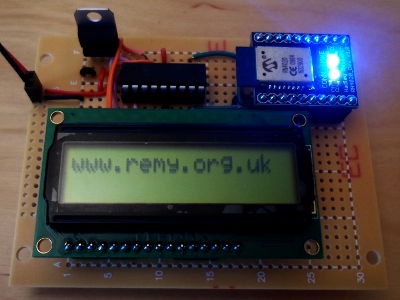
05 January 2018This board is a smaller-scale rebuild of my previous Bluetooth-enabled LCD display, and one I decided to make purely because it is the type of circuit I might want to carry around to show to others. It became possible because the 3-volt LCD display is a bit smaller than the 5-volt display I originally intended to use, and hence everything was able to fit within the foot-print of the integrated-circuit prototyping board. The circuit itself is not particularly complex, and this time round I had both a working reference and all the required components. As a result most of the remarks I will make are general ones not specific to this project.
Circuit layout
The headers for the RL4020 Bluetooth chip, mounted as before on a breadkout board, are wired to put the chip into RS232 command mode. The serial pins are wired to thePIC16LF88 microcontroller, although only the Tx pin needs to be connected as the firmware does not write anything to the serial connection — it is only included because I foresee possibly adding RL4020 setup to the firmware in the future. The microcontroller in turn is connected to the LCD display headers at the bottom of the board. As can be seen below, the wiring & component density is pretty low.
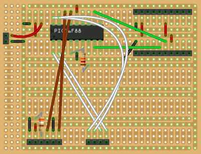
I left out the voltage regulator because Fritzing does not seem to have an option to change the pin assignments to match the LD1117V33C 3.3-volt regulators (Farnell 1703357) I stock, and I did not feel like putting in a place-holder. While I still have an overall positive view of Fritzing, I do feel that I am having to make allowances for deficiencies of varying severity when using it as a tool. Pity really as I feel the big design compromises it makes are good calls, and its faults ought to be simple fixes.
Choice of wire
Ease of soldering and material of components is something I have mentioned in the past, although in the latter case I was thinking of header pins & receptacles. For this circuit I broke into a new stock of equipment wire, which has a core of solid copper, and compared to most of the wire I have used previously it is a dream to solder — the molton solder sticks to the wire as readily as it sticks to the copper tracks on the breadboard, without needing to hold the soldering iron down for long. The wire I have mostly used until now is a stock I got off E-bay, and although I am not entirely sure what it is made from, I suspect it is tin-coated copper — my suspicions are helped because a small stock of what I knew was tinned copper had the same problems.Tin-plated copper is great for solderless breadboard because it does not tarnish, but for soldering it is a right pain, most notably the time it takes before the solder would attach itself to the wire. Since I always solder freshly-stripped wire, and hence there should be very little oxide on the wire for the flux to remove, I suspect it is due to the time it takes for the tin on the wire to start to melt — this is because the solder starts to attach to the copper breadboard tracks long before is starts to stick to the wire. The solderability of different types of electrical wire is something I tried reading into when I first started, but I could not find much useful information, let alone anything authorative. My working conclusion is that bare copper is the wire to use and that anything coated should be avoided.