STM32L4R5 Cortex-M4 firmware
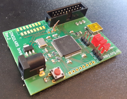
23 June 2024One of my lockdown-era projects was creating a mini breakout board for the ST Microelectronics
STM32L4R5 Cortex-M4 which in turn was a revision of a much earlier design of mine, but like many other things back then it got interrupted and had since lost track with how much it progressed.
Cannot remember the exact criteria used to select the chip back in 2018 but one of the factors in the balance was it having a relatively large amount of program flash and system memory.
Earlier this year I decided to revisit the firmware from scratch and in the process document in one place both bits of information that were spread all over the place, and new things I found out in the process of getting some of the interfaces working.
This article is the result.
A bit of background
The hardware design was mostly based on the reference circuit within one of the technical documents so is out of scope of this article, but in summary when this second revision was made it was the intention of trying out five functions: General Purpose I/O, UART (i.e. RS232), I2C, external clocking, and USB. For USB I have vague memories of programming it to be a host system rather than just a device but those months of early-2021 are now a bit of a blur with a lot of things being put on hold. There are other functions I would like to try but I did not know of them at the time and in any case a line has to be drawn somewhere. Knew figuring the chipset out would be a massive task having figured out the NXP LPC and Kinetis-KE series of Cortex-M0 microcontrollers, so motivation was rather short.Personal circumstances caused by Covid-19 lockdown meant that I had to give up what was a very nice job in embedded programming in favour of something that everyone knew was a means to an end, and I had started doing firmware projects again to stop myself getting too rusty. I don't consider my interest in Microchip PIC micro-controllers to have any professional value and I had pushed my projects based around NXP LPC and Kinetis-KE Cortex-M0 chips about as far as it could go, so it was time to move on to the Cortex-M4. Coincidentally I am “on the road” quite a lot these days and all the hardware needed is a very compact kit.
Development environment
In the past often as not at least some of the ARM development tool-chain had to be built from source tar-balls but these days reasonably up-to-date versions of all the tools are available through SlackBuilds and the easiest thing is to use SBoPkg to build & install them. They are mostly the GNU tool-chain configured as a cross-compiler and everything that is needed are available in these four packages: I am constantly forgetting the new extra commands needed to do stuff compared to workstation software development, so below are ways in which the important boiler-plate commands can be automated.Connecting OpenOCD
I use the OlimexARM-USB-TINY-H which is more or less a generic JTAG programmer & debugger tool.
In the past I used a shell script to run OpenOCD with the correct configuration files for both the tool and the microcontroller, but since then have instead made it into a Makefile rule.
Here it is assumed that it is using SWD (Serial Wire Debugging) but full JTAG can also be used by not using the SWD adapter and omitting the line mentioning olimex-arm-jtag-swd.cfg.
OCD_SCRIPTS=/opt/share/openocd/scripts ocd:: openocd \ -f $(SCRIPTS)/interface/ftdi/olimex-arm-usb-tiny-h.cfg \ -f $(SCRIPTS)/interface/ftdi/olimex-arm-jtag-swd.cfg \ -f $(SCRIPTS)/target/stm32l4x.cfg
By far the most common pit-fall is LIBUSB_ERROR_ACCESS error messages that is related to permissions, and this is solved by adding to /etc/udev/rules.d/ a file containing the following, and then once that is done running udevadm control --reload-rules followed by udevadm trigger.
SUBSYSTEM=="usb", ACTION=="add", ATTR{idProduct}=="002a", ATTR{idVendor}=="15ba", MODE="0666"
For some reason setting the permissions via UDev sometimes works in cases where using chmod 666 does not — why I do not know as OpenOCD is one of those things that suddently just starts working.
Flashing firmware
Once an OpenOCD connection has been established it is connected to via telnet and commands issued that cause the OpenOCD to download the firmware to the microcontroller. Unfortunatly I am not aware of command-line parameters to do the same task so instead an old trick from the days of modem dialup is used that automates the interactive flashing session, and this is also wrapped up as a Makefile rule:EXP_SCRIPT="" EXP_SCRIPT+='spawn telnet localhost 4444~' EXP_SCRIPT+="expect \"\\r> \"~" EXP_SCRIPT+="send \"program "$(BIN)" verify reset exit\\r\"~" EXP_SCRIPT+="expect eof" flash:: @echo $(EXP_SCRIPT) | sed 's/~/\n/g' | expect -
Attaching GDB
I often forget the boiler-plate commands needed to attach GDB via OpenOCD to a microcontroller, so as with starting up OpenOCD and flashing the firmware I made it into a Makefile rule as well, the choice of Makefile rules over scripts is it keeps as much as possible inside a single file although Makefiles do have a tendency to get a littly ugly.gdb: $(ARCH)-gdb -ex "target extended-remote localhost:3333" -ex "monitor reset halt" $(BIN)
A nice thing about having GDB attached is being able to use the make and load commands to build and upload firmware changes without leaving GDB itself, and restarting the program using the load command will execute the newly updated firmware.
STM32L4 firmware
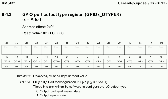
My recollection is having got at least GPIO working but the code and linker script in my Bitbucket repository was clearly broken, and decided it was much more expedient to look back to the technical documentation rather than go hunting for missing snippets of source. The hardest part of the effort was working out and getting used to how the technical documents present information, most notably the reference manualRM0432 only giving the offsets for registers and not mentioning what the base address.
An example is given below for GPIOx_OTYPER which controls whether an output pin is normal push-pull or is open-drain;
the secret is the base addresses are in the data-sheets which are much more model-specific.
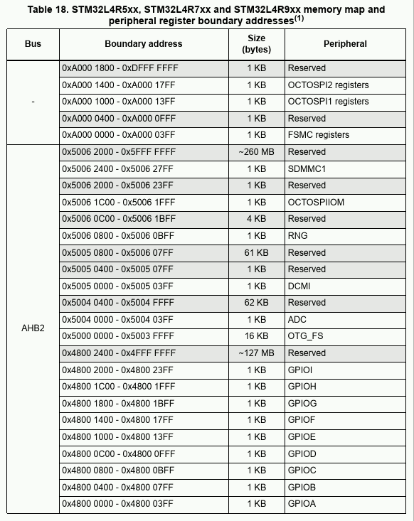
The breakout board has Port B pins 12 thru 16 wired to the on-board LEDs so it is base address GPIOB that needs to be found and to cut a long story short its value of 0x48000400 is in the data-sheet under Memory Mapping as shown in “Table 18” below.
This means the full register address for the output type register is 0x48000404.
This split of register addresses between reference manual and data-sheet is something I also saw with the other ARM Cortex chipsets I have used, unlike Microchip who with their PIC micro-controllers do not have seperate data-sheets and reference manuals.
Memory layout
Whereas the NXP LPC and Kinetis-KE chipsets I used previously always start execution at a section of flash memory at address zero, on theSTM32L4 this is actually a shadow part of memory that depending on boot mode aliaes different sections of the address space.
This can be the main block of flash memory; it can be one of the SRAM blocks after a piece of stub code has written out the vector table; or it can be “system memory” which contains a boot loader that can do things like boot over a serial connection.
Yes it still boots from address zero but when programming over JTAG the shadowing is not setup and it instead goes into a block of flash memory located elsewhere.
BOOT0 jumpers
Where the boot area of the address space actually aliases is dependent on multiple things but one of them is an external pin which thankfully I had broken out for a jumper but had never soldered the jumper pins in place. Turns out there is no internal pull-down or pull-up so the boot mode was being random until I bridged the pin to ground with some wire. For some reason if the floating voltage was detected as a ‘high’ which is I think meant it used the internal boot-loader, the LED attached to pin 52 (port B bit 12) was being lit. Whatever the reason this might be why I thought there was already a working firmware on the board from when it was assembled back in early-2021.Peripheral clocking
As well as functions being switched on and off via an ‘enable’ register bit they also have their clocks gated as well, and this gating is controlled by the RCC (Reset and Clock Control) module. For example clocking of general purpose I/O on Port B is enabled byGPIOBEN which is within AHB2 peripheral clock enable register RCC_AHB2ENR which has offset 0x4c.
The base address for RCC is 0x40021000 so enabling the clock is done using register address 0x4002104c.
Not much different from the general purppose I/O example above but it is still tricky figuring out all the names and acronyms.
Functions being gated by default seems to be almost universal across all ARM Cortex core chipsets, which is presumably to allow them to compete with the power consumption of simpler parts such as Microcliop PICs, though the STM32L4 is a little unusual in having general purpose I/O off by default.
One things that caught me out with another chipset was the module that controlled the gating of some functions was itself gated!
It is all minor variations of the same scheme but going digging for that one extra register address while not difficult is certainly time-consuming.
General Purpose I/O
There is not much to say about General Purpose I/O as it is the bread-and-butter bit-banging and reading of pins. The GPIO unit is gated by default and pins start out in analogue mode, and as well the basic value read/write also registers for setting and clearing specific bits which is nice as it means not having to do bit-masking. One thing to watch out for is the GPIO module also controls the mode of pins, so for things like RS232 it has to be enabled for the appropriate port so the pins can be changes over to “alternative“ functionality. I did not test whether the GPIO module can be gated once the setting has been made but I suspect it can be.Timer module
Basic use of the 32-bit Timer2 was done to generate one-off user-perceptible delays and on the whole it does not need many registers to be set, but it does come with one big gotcha/ It seems that the timer has to go through a cycle of being triggered before all the settings become active, which I am not sure if it is intentional but I suspect it is since I read some bits about buffering of register values, but have not worked out how to disable such buffering. Guessing all these options make sense because the same function does things like pulse-code modulation. Timer2 was one of the general purpose timers and it seemed pretty complicated as-is so I dread what the advanced control timers are like.RS232 serial communications
Technically this should really be called UART/USART as RS232 is normally refers to the high-voltage electrical interface used between computers and devices, but theSTM32L4 USART actually does more than just basic serial communications.
It also does SPI which is something that Microchip micro-controllers instead do through their I2C modules, with the STM32L4 “USART” also having options for things like use with irDA and smartcards.
However for basic one-byte-at-a-time transmission and reception the only tricky bit is accounting for the various pre-scalers in the clock path when calculating the BAUD rate.
Using interrupts
Rather than my usual polling loop I decided to try using interrupts with RS232 instead, which meant having to go digging to work out what was stopping the interrupt hitting the jump table. At first I thought it might be a gated clock but enabling of interrupts is within the ARM core itself which is covered in the Programming manualPM0214 rather than the reference manual.
I suspect the programming manual is common to all Cortex-M0 based microcontrollers but it looks like ST Microelectronics reformatted it for their own documentation style.
Other microcontroller functionalities
There are other chipset functionalities that the breakout board is designed for but at time of writing I have not got round to getting them working, but at least as far as firmware is concerned it would be much the same story of chasing down various registers that need to be set for things to become operational. It is easier to just update my ARM code repository as and when I figure stuff out, particularly as any project I am likely to start any time soon will most likley use a chipset other than theSTM32L4.
- External clocking
- After headaches with just trying to find out what the default speed was on Kinetis KE Cortex-M0s the nice thing about eternal clocking is the complete absence of parameters other than enabled/disabled, and once enabled there is no doubt what the actual clock speed is. However I was unable to get it working on this board, which after probing with an oscilloscope I suspect is down to a fault with the oscillator chip. There might also be start-up transcients that are not being accounted for, but at the moment that does not appear to be the blocking problem.
- I2C serial communications
- Deriving the value for the
STM32L4I2C timing register is undocumented with ST parroting that people should use their STM32CubeMX tool, which includes blindly giving rise and fall times of zero. Aside from this the register bits relevant to transactions don't seem vastly different to those on the NXP and Microchip microcontrollers, which amounts to not much more than when start/restart/stop bits should be emitted/expected. - USB connectivity
- The STM32L4 can act as both a USB device and a USB host so even with the knowledge of getting USB operational on the
LPC11Uxxchipset working everything out will be a massive project. This one will be at least an article in itself.
Remarks
Every chipset has its quirks but in this case a major issue is not having done any from-scratch ARM firmware development since Covid struck. Yes getting USB working on the NXPLPC11Uxx chipset was no trivial project, but almost all the gotchas such as of making sure everything was being clocked was within the first six weeks of 2020 if not earlier.
One of the very few things of that year I can look back at without bucket-loads of regret, let alone fondness.