17-segment LED display
21 April 2018I recently came across some Kingbright
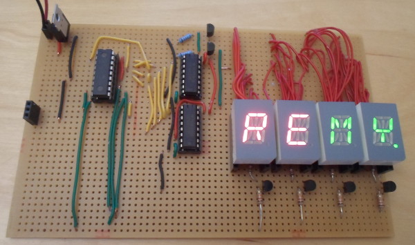
PSC05-11CGKWA 16-segment LED chips (Farnell 2373489) and somewhat impulsively decided to give them a try, and to do so I built a circuit with a 4-chip array. In this circuit 74HC238 3bit-to-8bit expanders were used to aid the LED blinking process, and a PIC16F88 microcontroller was used to coordinate the displays. I was originally going to use a PCB, but in the end decided to use prototyping board instead, as this was a bit of fun rather than a serious attempt at making a re-useable component.
PCB vs. prototype board
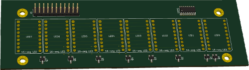
My original intention was to make an I2C-driven daughterboard that carried eight of the LED chips, but it was proving somewhat complex to design — it was only feasible at all because I realised that it was possible to squeeze in tracks between the 2.54mm through-holes, but that still left issues with connecting up everything else that needed to be on the board, such as the expander and the sinking transistors. At approximately 45cm2 already it would most likely cost around €30-40 to get it fabricated, and that was assuming I did not switch from two to four copper layers. I had thought about making a smaller PCB that used only two or four LED chips, but soon concluded that eight was the absolute minimum for a useful display.
In the end I concluded that in practice an off-the-shelf LCD display would be a better option as a component within a larger project, so this project was really just about experimenting with the LED chips. Since I had through-hole versions of all the components I intended to use, I decided to just use strip-board and get started on actually building the circuit. Doing a hybrid PCB & prototyping board circuit seemed like it would cause more problems than it would solve, and in any case did not want to wait a few weeks for the fabrication turn-around.
LED current & brightness
The data-sheet for the LED chips hints at a recommended current draw of 10mA, but the only firm numbers are the maximum power ratings, which are not really suitable as circuit target values. In any case I decided that trying to translate between constant-power and pulsed-power electrical values had too many pit-falls, so I decided to find out the best resistors to use experimentally in a test circuit that actually used pulsing. APIC16F630 is programmed to emit a 1ms pulse on the PORTC pins with a 10% cycle (i.e. on 1ms and then off 9ms), which is used to control a NPN sinking transistor. The resistors on the left-hand side of the LED chip from top to bottom are 1kΩ, 2kΩ, 5.5kΩ and 10kΩ, whereas the one to the right is 380Ω — in other words going from top to bottom of the F shape is increasing resistance, and hence decreasing current. The circuit power supply is a nominal 5 volts.
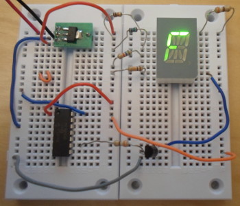
The picture does not do justice to the relative brightness of the segments, aside from showing 380Ω being substantially brighter than all the others. 10kΩ was in reality far too dim and 5.5kΩ was a bit too dim for my liking, whereas 1-2kΩ seem to be ideal brightness. 4.7kΩ may have been alright, but I did not have one at hand to test with. Since the power to the segments was being pulsed, I measured the current using both AC and DC modes of the multi-meter — the 1kΩ resistor had a current draw of 0.97mA (1.19mA AC) and the 2kΩ had 0.47mA (0.57mA AC). Both of these are about half of what I expected, but thede values are not what I was realy interested in. Assuming this test circuit setup is representative of the LED driver circuit, a 1kΩ resisitor is the one to use with this particular LED chip.
Design
I knew from the outset that the trickiest part would be wiring up the LED chip receptacles, and this is a situation where Fritzing shows its value, even if the tendency is for it to only be used for rough laying out. For this circuit I made an effort to keep the Fritzing design in sync with the physical circuit, because although there are deviations, the connections are nevertheless a lot clearer. Even though my main stock of circuit wire is red so this was what I used for the LED chip connections, for the other wires I decided to colour-code them for clarity.
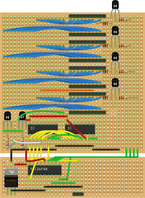
Normally when using ICs a lot of wiring is required to match the pin-outs with what they need to be connected to, but in this case the 74HC238 chips could be dropped straight onto the unaltered tracks that the LED chips are wired to — contrast this with the connection between them and the PIC16F88, which has both cross wires and wires going around to the other side of the chip.
Segment cycling
In contrast to the previous circuits using LED chips, in this circuit the segments are blinked in turn, with the LED chips being enabled/disabled as needed. This is because there are sixteen segments versus four chips, and it is logistically simpler for the larger number of segments to be cycled while controlling the chip, rather than the other way round. One consequence of this is that at most only one segment per chip will be lit, although the same segment on a different chip may also be lit, so current-limiting resistors are connected to the common ground pin.Decoder wiring
Although I did have a 4-to-16 decoder it was a surface-mount chip, so instead I used two74HC238 3-to-8 decoders to achieve the same effect. When I first came across the latter I thought it was odd that it had three enable/disable pins, but after this circuit I understand the logic of having them. The schematic below shows how they were wired up, with bit B3 acting as a chip select. B4 corresponds to the 17th segment that is powered be a separate transistor pair rather than either of the two decoders, since there are not enough decoder outputs, so in this case both of the latter are disabled.
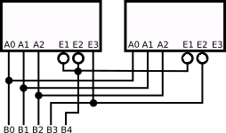
The 17th segment is powered by a Sziklai NPN-PNP transistor pair — not shown in the diagram above — rather than a direct connection in order to provide electrical isolation, with the 78.7kΩ base resistor notionally being comparable to the high- impedence of the 74HC238 inputs. As a result there is not a huge surge in current drawn from the microcontroller when this particular segment activates. My original plan was that the decimal point segment should be wired to the NPN-PNP pair, but doing so would have meant extra track cutting & wiring, and I concluded it easier to do the swapping in firmware.
Resisitor ratings
The most important resistance value is that determining the current out of each LED chip, and for this the limiting factor turned out to be the 25mA that the74HC238 can output per-pin (total power draw is irrelevant as only one output will be used at once), which works out at 6mA for each of the four LED chips. Assuming a 3-volt drop this means this resistance needs to be at least 500Ω, but I decided to go with the 1kΩ value that the brightness tests suggested. In practice this turned out well even though there was a 1:17 duty cycle rather than 1:10 as in the brightness test. The sinking NPN transistors use my standard choice of 12kΩ base resistance, which allows a collector current vastly in excess of what the above 1kΩ LED resistance would draw. The Sziklai pair use 78.7kΩ as the base resistance as this input is intentionally of high impedence. The base-emitter resistor on the PNP transistor within this pair is for technical correctness as the base is floating when the NPN transistor is “off”, although from what I read this is unlikely to make any practical difference given the voltage and frequency it is operating at.
Receptacle cost
A long-standing issue I have had is the relative cost of receptacles, because away from a few common sizes — always even and usually a power-of-two — they are insanely expensive for what they are, and often as not have to be bought in bulk. For example 4-way and 6-way receptacles are about 21¢ each, whereas single-pin ones are the most expensive I have ever stocked at €1.09 each. A while back I invested in a large stock of 3-way receptacles, although this is only justified by the frequency that I include 3-wire I2C interfaces on my prototype boards. I have tried buying long & cheap receptacles off E-bay and breaking them into smaller lengths, but as has often been the case with components sourced this way, the results has typically been not quite satisfactory.At €2.53 each I did not want to permanently solder the LED chips into this board, but to use two 9-way receptacles at 91¢ each to me was not a worth-while trade-off. For this circuit I instead used 10-way receptacles (21¢ each) because I needed to have wires underneath the LED chips, but in general this is a solution I hate using — I only opted for it because of the potentially high probability that I would not complete the circuit, as I abandoned a similar project with 7-segment LED chips in the recent-ish past.