I2C primer
24 August 2017One thing that became apparent quite quickly from my LED display project is that parallel data lines between components is a right pain, and since then I2C came onto my radar a common intra-curcuit communication system. As a result I2C is something I needed to investigate, and this article is my collection of notes from doing so. Robot Electronics over in the UK give a good overview of I2C, but for those who already have some background knowledge of RS232/RS485, the main points can be summerised as follows:
- Multiple devices
- Like RS485 but unlike RS232, I2C supports more than point-to-point communications between two devices. Multiple devices share common signal wires, and each has its own address.
- Master-slave architecture
- Only master devices can initiate transactions, so if a slave has data to transmit it either needs to be polled, or have some out-of-band way of notifying the master. Typically there is only one master, although some devices do support multi-master arrangments.
- Bus & clock signals
- Rather than Transmit & Receive, there are clock and data signal lines. One advantage of this is that slaves don't need any manual setting of ransmission speed, which is a major headache with RS232/RS485.
- No cross-over
- Unlike RS232 there is no crossing over of terminals between devices. All SDA (data) terminals connect to the SDA wire, and all SDL (address) terminals to the SDL wire.
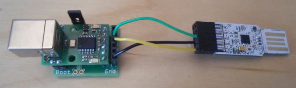
USB-ISS-SV I2C which acts as a I2C master, and as far as I can tell is the only I2C-to-USB master-device adapter out there that is not above $100. In hindsight I should have got USB-ISS I2C instead as the downward-facing pins on the SV variant are a bit too short for solderless breadboard, although I got round this by making my own breakout daughterboard which is shown in the picture below of the two devices connected together (USB-ISS on left, UMFT201 on right).
Robot Electronics USB-ISS
The USB-ISS only operates as an I2C master, and is incompatible with multi-master setups. When plugged in under Linux it appears as /dev/ttyACMx, which can be treated in the same way as any other tty (i.e. serial) interface. Setting serial parameters such as buad and parity via the likes of setserial has no effects — I2C parameters are set using a different mechanism. Rather than just pumping data to/from the USB-ISS, a request-reply control protocol is used over the USB connection, for which the details are in the USB-ISS specs. It is a pretty basic binary protocol that consists of a single-byte operator, between 1-5 single-byte operands, and if applicable any payload bytes. For I2C the following are sufficent:
| Operator | Operands | Payload | |||
0x5a |
0x02 |
0x60 (h/w 100kHz I2C) |
0x04 (binary I/O) |
||
0x53 |
Device address & R/W bit | Data byte | |||
0x54 |
Device address & R/W bit | Byte count | Data byte(s) | ||
0x55 |
Device address & R/W bit | Register address | Byte count | Data byte(s) | |
0x56 |
Device & R/W bit | Register address (hi word) | Register address (lo word) | Byte count | Data byte(s) |
0x57 |
|||||
The first instruction (operator 0x5a) enables hardware I2C operating at 100kHz, which most likley is what you want — see the USB-ISS specs if you need further details. This only needs to be done once when the adapter is powered up, and the instruction can be sent from the console using the following command (assuming appropriate permissions on /dev/ttyACM0):
./ttyTxRx.py /dev/ttyACM0 2 5a 02 60 04
The middle instructions (operators 0x53 to 0x56) are all read/write commands. The low bit of the device address indicates whether an operation is a read rather than a write (i.e. odd addresses are reads; even addresses are writes), and some devices do not need some of the operands (e.g. 0x53 is for devices that only have a single byte that can be accessed). Hence to write to device with address 0x22 the single byte value 0xcc) you could use:
./ttyTxRx.py /dev/ttyACM0 1 53 22 cc
The last instruction (operator 0x5a) is for constructing a custom I2C sequence, which is covered below.
Return values
After a command has been written to the USB-ISS return values can be read from the serial device. There is always at least one, and this first one is usually a status byte with zero for failure and non-zero (0x01 for I2C writes and 0xff for other commands) for success. One annoying this is that I2C reads will on error return 0xff in place of expected data, so if you needs to distinguish between an actual 0xff byte on the wire and an error, you will need to use a custom I2C sequence.
Custom I2C sequences
To create a custom I2C command that goes beyond simple reading or writing, a mini-protocol is used to build up the I2C sequence, which is then processed in one go. Some background of how I2C communication sequences are constructed is required, but this does not require knowledge of wire-line voltage levels. The one oddity in the I2C standard is needing the I2C master to Nack the final byte of a read, hence the send nack after next read command, but apparently this is not strictly required. A more complete description is included in the USB-ISS specification, but a summary of the commands used in the mini-protocol is shown below:
| Operator | Description |
0x57 |
Begin custom I2C command |
0x01 |
Send start |
0x02 |
Send restart |
0x03 |
Send stop |
0x04 |
Send Nack after next read |
0x2n |
Read n+1 bytes |
0x3n |
Write n+1 bytes |
Once the full command has been written, at least two bytes will become available to read. On success this will be 0xff followed by a byte count, and if the latter is non-zero (which will be the case if there were any read operators) this number of bytes will follow. In the case of failure, the two bytes will be 0x00 followed by a single-byte error code. An example sequence is shown later in this article.
FDTI UMFT201XB-01
The UMFT201 is a slave-only device which appears as/dev/ttyUSBx, which conveniently is a different naming scheme used by the USB-ISS, but may still be a headache if you have other USB-serial adapters plugged in. Being a slave device there is basically nothing to configure, but if you want to use an I2C address other than 0x22 (according to the data-sheet — by experimentation I found my device actually used 0x44 so I will use the latter in my code snippets), you have to change the Internal MTP Memory. The “easy” way is to use the FT_PROG utility (user guide) to change it, but unfortunately the utility is Windows-only and comes with the caveat that it might brick the device. The MTP memory can also be changed via the I2C interface (see section 10.2.2 of data sheet), but this will involve some experimentation as the data sheet does not give an explicit list of parameter address values.
The device itself operates at 3.3volts but is tolerant of 5volt input, and being a slave device the clock speed of communications is dictated by the external I2C master. From the computer's point of view the device can be read and written just like any other serial device. There are receive and send buffers, and the device will a NACK read/write from the I2C master if the status of the buffer — an empty out-bound buffer on a read or a full in-bound buffer on a write — precludes servicing of the request.
Querying the out-bound buffer
The UMFT201 provides a mechanism that allows an I2C master to find out how much data (if any) is available for reading, which is detailed in Section 9.3 of the data-sheet. This involves using the General Call Address (GCA) of0x00 followed by a device-specific Read Data Available (RDA) command, which will cause the next read cycle to return a byte that indicates how many bytes are available for a burst read. The table below shows the I2C communication sequence, and shows its approximate conversion into a USB-ICC custom I2C sequence (the UMFT201 slave address of 0x44 is assumed):
| Start | GCA | Read | Ack | RDA | Read | Ack | Restart | Address | Write | Ack | Byte count | Nack | Stop |
| Start | Write sequence (2 bytes) | Restart | Read request (1 byte then Nack) | Stop | |||||||||
0x57 0x01 |
0x31 0x00 0x0c |
0x02 |
0x30 0x45 |
0x04 0x20 |
Stop | ||||||||
From the Linux command-line, and assuming appropriate permissions on /dev/ttyUSB0, this query can be performed using the following commands:
./ttyTxRx.py /dev/ttyACM0 3 57 01 31 00 0c 02 30 45 04 20
On success you should get 0xff01 for the first two bytes and the third byte is number of octets available for reading. Some of the UMFT201 output pins can be setup to indicate whether the buffers are empty/full, but I have not looked into how these are enabled.
USB-to-USB test
As a first excercise in trying out I2C without the complication of building a circuit, wire them together as shown at the top of the article and run the following commands in order. The payload0xcd sent from the master should appear on the slave, and then the 0xdeadbeef sent from the slave shold appear on the master.
./ttyTxRx.py /dev/ttyUSB0 1 de ad be ef ./ttyTxRx.py /dev/ttyACM0 1 53 44 cd ./ttyTxRx.py /dev/ttyACM0 4 54 45 4
May well need to run the first command in a seperate window as it will probably block.
Hardware test
As a test of I2C on hardware, I wired up a PCF8574 I/O expander — detailed later in this article — to drive a bank of LEDs. This is the simplest hardware-orientated test of I2C I could think of, and the completed circuit is shown below. Keep in mind that the for this particular expander the LEDs need to be connected between the pins and Vcc/Vdd (positive power rail), rather than between the pins and ground (Vss).
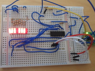
The upper four bits of the device's address are fixed leaving the remaining three bits to be set via IC pins, and in this case the middle address pin is tied to Vcc and the other two tied to ground, giving a write address of 0x44 (see 8.3.2 of the data-sheet for a lookup table). Assuming that the expander is being driven by a USB-ISS I2C master connected to /dev/ttyACM0, you should be able to run these two commands and see the LEDs change.
echo -en '\x5a\x02\x60\x04' > /dev/ttyACM0 echo -en '\x53\x44\xcc' > /dev/ttyACM0
The first command sets up the USB-ISS master, and only needs to be run once. Within the second one the two payload bytes of 0x44 & 0xcc are the address and pin-out values respectively, the latter final byte (0xcc) being the one that indicates which LEDs will be lit.
I/O Expander chips
An I/O expander is basically a parallel-to-serial converter, so called as it allows a Microcontroller with only a few pins to have a large number of input/output conections. So far the TI PCF8574 and the Microchip MCP23017 are two that I have sourced. General impression is that the PCF8574 is aimed as a zero-configuration part for driving loads, whereas the MCP23017 is a much more flexible one aimed at providing a Microcontroller firmware with data connections.PCF8574 (8-bit I/O Expander)
The simplest I/O expander I have found so far is the Texas Instruments PCF8574 (Farnell 2335655, datasheet), which is I2C-based. It does not use internal addressing and as far as I can tell the GPIO pins switch between input & output automatically — the I2C master simply needs to send single-byte read or writes. There are a few caveats with this particular expander though:- Sinking output
- The expander is meant to go on the low side of circuit loads, where it acts as ground. It doesn't provide positive voltage.
- Zero is on
- Current flows when an output pin is set to logical zero, with logical one being an open curcuit.
- Three address pins
- Limits you to 8 devices on same I2C bus, with remaining address bits being fixed.
MCP23017 (16-bit I/O Expander)
The Microchip MCP23017 (Farnell 1332088, datasheet) I2C-based I/O expander consists of two 8-bit “banks” of GPIO pins for a total of 16 inputs/outputs. Communication via I2C accesses the internal registers, so in the I2C frames a register address needs to be specified, and for good measure the address of the registers depends on which of two addressing schemes is in use: Group by function, or group by associated bank. TheIODIRA & IODIRB registers control whether pins are inputs and outputs, and both are initially set to 0xff (all pins are inputs). All other registers are set to 0x00, which implies IOCON.BANK is cleared, and hence registers are grouped by function. Therefore for output the following four registers need to be set:
| Register Name | Address | Value | Description |
| IODIRA | 0x00 | 0x00 | Set all Bank A pins to output |
| IODIRB | 0x01 | 0x00 | Set all Bank B pins to output |
| GPIOA | 0x12 | bitmask | Set value for pins 21-28 (Bank A) |
| GPIOB | 0x13 | bitmask | Set value for pins 1-8 (Bank B) |
Pin associations will be different for the non-DIP variants of the IC package. My feeling is that the configurability, which includes things like being able to invert inputs and setup interrupts, is a double-edged sword — while much more flexible it also means the device requires configuration, which in some circumstances can be a pain. To me the main advantages of this one over the TI PCF8574 expander are twice as many I/O pins, a much higher speed I2C interface, and — surprisingly — somewhat lower cost.
Python test program
While it is possible to write directly to the serial interfaces using Linux shell commands, such as is done in the expander example, reading serial data and displaying it to the console is a bit of a pain. To simplify things I have written a small Python script — code below — that transmits hexadecimal bytes given on the command-line, and then reading & prints out a specified number of received bytes.- ttyTxRx.py
- #!/usr/bin/env python import serial,sys if len(sys.argv) < 2: print "USAGE: {0}
[outgoing bytes]".format( sys.argv[0] ) sys.exit(1) cntExpectBytes = int(sys.argv[2]) i2c = serial.Serial(sys.argv[1]) if len(sys.argv) > 3: packet = b'' for octet in sys.argv[3:]: bite = chr(int(octet,16)) packet += bite print "Sending {0} bytes..".format(len(packet)) i2c.write(packet) if cntExpectBytes > 0: print "Replies ({0} expected):".format(cntExpectBytes), bites = i2c.read(cntExpectBytes) for bite in bites: print hex(ord(bite)), print - #!/usr/bin/env python import serial,sys if len(sys.argv) < 2: print "USAGE: {0}
pip install pyserial (maybe within a virtualenv but that is well beyond the scope of this article) to get access to the serial library, but everything else should be part of the standard Python distribution. The script commands are as follows:
./ttyTxRx.py <tty device> <num bytes to read> [byte(s) to write]
So to write three hex bytes (0x00, 0xcc, & 0xff) to /dev/ttyUSB0 and then read back 2 bytes, the following would be used:
./ttyTxRx.py /dev/ttyUSB0 2 00 cc ff
For clarity there is only minimal error handling, but Python's exception system will mean errors will be obvious.