I2C slave device
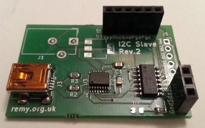
17 January 2021A significant issue I had with my redesigned USB-I2C master was testing and in particular the checking of error conditions, so I decided to make a test platform for this purpose. Originally I was going to make a dedicated board including DIP switches but I soon realised that test configuration could also be done via the I2C connection, so instead I built the hardware as a break-out board since the
PIC16F1823 with RS232 and I2C is a common combination I use as a base for projects.
Circuit design
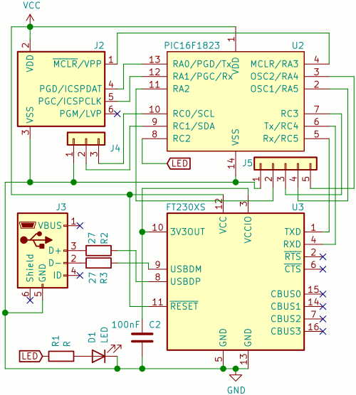
The circuit itself is the I2C master with a 14-pinPIC16F1823 rather than an 8-pin PIC12(L)F1840, and the circuit is powered via an on-board voltage regulator supplied via a barrel jack rather than the USB bus.
A flash header is also included because it is by far the most convenient way to reprogram a microcontroller, and all the unused I/O pins have been fanned out.
Note that between the PIC16F1823 and the FT230XS the RS232 pins are connected Tx-Rx & Rx-Tx and not Tx-Tx & Rx-Rx — getting this wrong is why the PCB went to a second revision.
An ulterior motive with this project was creating a KiCad footprint for the PIC16F1823 and this in turn is based on the foorprint for the PIC12F1822 from the same chip series.
Several of my recent projects would have used PIC16F1823 if it was not for the absence of the footprint in the standard library, so it was time I got round to making my own.
This footprint is included alongside the PCB itself within my Bitbucket repository.
List of components
I found it hard to see the cathode markings on the OsramLM R976 SMD LEDs and as a result had soldered some of them the wrong way round, and the CUI Devices PJ-102AH barrel jacks are also tricky to source, but they are components I had at hand so decided to use them up.
| Pad | Component | Manufacturer | Part number |
| U1 | 5v power regulator | Texas Instruments | UA78M05IDCYR |
| U2 | Microcontroller | Microchip | PIC16F1823 |
| U3 | USB-RS232 converter | FTDI | FT230XS |
| R1 | 1kΩ protective resistor | Multicomp | MCWR08X1001FTL |
| R2,R3 | 27Ω USB resistors | MCWR08X27R0FTL |
|
| D1 | Indicator LED | Osram | LS R976 |
| C1,C2 | 0.1μF bypass capacitor | Samsung | CL21B104KACNNNC |
| J1 | Barrel Jack | CUI Devices | PJ-102AH |
| J4 | Pin header | Multicomp | 2211S-22G |
| J5 | 6-way receptacle | 2212S-06SG-85 |
Firmware
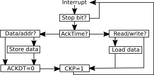
Whereas the I2C routines that were used within my I2C master have long since been rewritten in assembly and used in many subsequent projects, the same is not the case with the I2C slave routines I have written as I have preferred to use RS232 instead. Therefore the firmware here is a reimplementation in assembly of the routines in the register-enabled slave from late-2018, which I decided to do from scratch. The procedures are summerised in the flow-chart below. Storing of incoming data can be done on either branch of the Acknowledge Time node but I found it more convenient to do it before dispatching the acknowledgment.
Start and stop bits
I did not quite figure out start bit interrupts but I also saw no real need for them either. However getting interrupts for stop bits is useful because it helps in distinguishing between start and restart bits, which in turn can be used to allow a device to support a variable number of register addresses in read transactions. They can also be used as an end-of-transaction indicator rather than assuming fixed transaction lengths.USB side-channel
I have found it very useful to have a serial side-channel as a way of getting debugging information to the outside world, which is particularly critical in cases like this where using simulation is not an option. When I wrote the first version of the slave firmware I was having to deduce internal state rather than being able to probe it directly, which makes things very difficult. Having used the side-channel for development I left in tidied-up versions of the debugging messages, and an example transaction log is shown below:A:20 D:0a D:0b A:21 R:a R:a P
Here
A is an incoming address byte value, D an incoming data byte, R is the ack/nack status of an outgoing byte, and P is a stop bit.
Such use of RS232 in this way is also a good demonstration of the usefulness of clock stretching in I2C — without it I doubt that the UART transactions to print out the information would complete in time to avoid a buffer collision.
Address hold
Normally the microcontroller hardware automatically acknowledges incoming bytes, but by using address hold this decision on whether a matching I2C address should be acknowledged is instead passed on to the firmware. When I first tried implementing address holding back in late-2018 it seemed to be broken and looking back the symptoms of the fault it could plausibly have been an issue with whatever chip I was using. Having said that I did not consider the feature useful at the time so my investigation into it was limited. I still don't really see much use for it beyond testing some of the failure paths in the complimentary I2C master firmware, and for those tests I simply hard-coded the negative-acknowledge for the test-cases.Data hold
Like address hold, data hold lets the firmware decide whether a data byte should be acknowledged or not. Although unlike address hold it seemed to work properly in the previous firmware in hindsight I am not entirely sure whether how things were done was entirety correct, although this is a moot point as I don't write PIC firmware in C any more. For testing purposes incoming data bytes of0xff are not acknowledged which is sufficient to test most of the failure reporting cases.
Remarks
Partly due to the design of the circuit being a bit rushed I got the internal RS232 connection between the USB converter and the microcontroller the wrong way round, which by any measure was a frustrating mistake to make. As a result the firmware development and testing of my I2C master was instead done using an alternative board equipped with aPIC16F1454 back in November, which thankfully needed very few changes to make it work with the PIC16F1823 once the revised PCB for the latter arrived.
I did not have a 5-volt regulator to hand so I omitted the internal power supply and instead powered the slave via the ICSP header.
I tested the slave device with an off-the-shelf I2C adapter and then used this slave to test my own I2C master — in the process I found several faults with the latter's firmware which have now been fixed. While I have not noticed problems with my previous C-based I2C master and I2C slave routines I have more confidence in the correctness of my new assembly-based ones. The one thing the firmware does not guard against is spurious behaviour when pull-up resistors in place, but I think this is not possible to do and would explain why off-the-shelf adapters have built-in ones that cannot be disabled. I suspect that at some point I will reimplement my LED Matrix Tile firmware in pure assembly as it is the last bit of firmware written in C that I expect to have future interest in.