Self-made RF modules
17 March 2019Originally my article on wireless counting buttons was to also include RF (Radio Frequency) modules I made myself as well as off-the-shelf ones, but I then decided to put them into a seperate article — this is because the modules I made myself, aside from some basic testing, were not actually used to complete the previous project. In the longer-term I did not want to rely on self-contained third-party RF modules but this meant gaining experience with RF circuits, and this article covers the evolution of this experience.
Drop-in replacements
Rather than relying on off-the-shelf modules as I did in the previous article, I wanted to potentially have RF circuitry built straight onto a single PCB, so the next logical step was making my own RF daughter-boards which could be used in place of the off-the-shelf RF modules on my bootstrap circuits — this incremental approach was the only realistic one given that these prototype circuits were the only test equipment I had. Ultimately the real purpose of these PCBs was to gain some confidence in designing radio-frequency circuits — it was a case of follow what guidelines I could find and see if the result worked.Transmission module
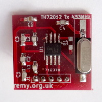
I designed an RF transmission module built around the MelexisTH72012 based on the test schematic within the data sheet, the complete PCB is shown below — I chose this transmitter chip since it can operate with both 3.3v and 5v power supplies. When I patched it into the prototype transmission board in place of the off-the-shelf module it just worked, which was very satisfying as I had no idea if it would actually work. The board could have very easily been made a bit smaller, but at the time size was not a real concern of mine.
Reception module
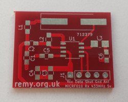
At the same time I also designed a receiver board based around the Micra (now part of Microchip)MICRF010 RF chip, but due to circumstances I never populated any of the PCBs I had fabricated — an unpopulated PCB is shown below. Seeing the transmitter PCB work gave me enough confidence in my RF circuit design to push ahead with investing effort in a combined receive & send module, and as a result I felt there was no need for a receive-only board. I did have a vague idea about using these two boards together making use of a Skyworks Solutions AS179-92LF RF switch in order to allow both to use the same antenna, but that idea was abandoned before development got that far.
Combined Tx & Rx board
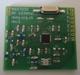
Although I had considered using seperate transmit and receive chips and have them use a common antenna, I eventually concluded that using a combined chip was a preferred solution, and after a lot of searching and re-searching was convinced that that the MaximMAX7030 (Farnell 2800969) was the only suitable such chip — there were other two-way chips out there, but none of them were purely transceiver chips. At €5.80 each they were quite expensive but the cost seems to have been reduced since I ordered in my samples. The data-sheet included a schematic which I implemented as shown below. The board is a lot bigger than it really needed to be, but at the time I was once again more concerned with getting things working. Much to my delight it just worked patching it into both my prototype transmitter and receiver boards.
Component headaches
The main complication with theMAX7030 is that it requires components that turned out to be particularly hard — and in a few cases expensive — to source. Most troublesome was needing a 17.63416MHz crystal that even Digi-Key did not stock, and it was only by luck that I found out that Mouser stocked a 17.63417MHz crystal (Crystek 017301, Stock code 549-017301) that I hoped would be close enough. Finding a Murata 10.7MHz ceramic filter was almost as troublesome although I located SFECF10M7HA00-R0 (Digi-Key 490-4682-1-ND) and SFECF10M7DF00-R0 (Digi-Key 490-4678-1-ND), and used the latter since it was the cheaper of the two — I had no idea if the differences between the two mattered so ordered in both. Sourcing all the capacitors and inductors was also an ordeal, with 16nH being particularly difficult — the 0805-sized (2012 metric) ones were of unreasonable cost of €1.40 each on Farnell so I used a 0603-sized one instead. For revision 2 of the board I sourced some 0805-sized 16nH inductors from Digi-Key as 0603 is that bit too small for me.
Prototype two-way board
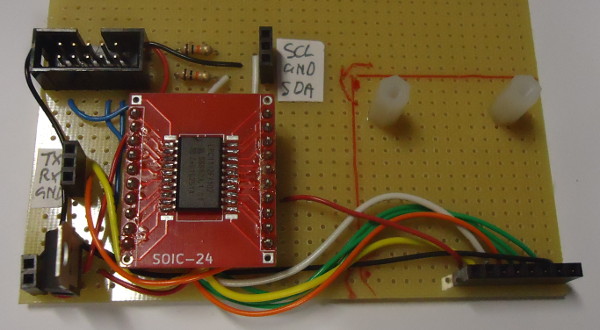
After headaches with the firmware for the prototype reception board I was already skeptical whether a PIC microcontroller was really up to the task of robust wireless reception, and after seeing how many banks the data memory on thePIC16F1829 is spread over I simply concluded that it was more trouble than it was worth. Instead I decided that I would use an NXP LPC1112 (an ARM Cortex-M0 microcontroller), particularly as the cost difference between it and the PIC offerings was minimal, and I could write the firmware in C with proper debugging tools. Although at time of writing I had created a host board for the bi-directional RF PCB — which is shown in the image below — due to delays ordering in an adapter for the programming interface I have not been able to make any use of it, and therefore will make it a subject of a future article.