First ARM Cortex-M0 firmware
13 August 2018This article is the firmware complement to my electronics article Bootstrapping ARM Cortex-M0, and will consist of a very basic firmware written in C. This firmware will be compiled using the GNU ARM tool-chain on a Slackware 14.2 desktop system, and then flashed to an NXP
LPC1112 using OpenOCD via an Olimex ARM-USB-Tiny-H debugger. The focus is on a minimalist example to get things going, rather than an in-depth explaination of what is going on.
The way I work things out is to find notionally working examples, tear them to bits to work out what they are doing, and then trying to build my own minimalist example based on my understanding of what is going on — below is the outcome of this process. The most useful resource I came across was the Cortex-M bare metal example, but with cross-referencing to Catch22's Baremetal LPC11xx and David Welch's stm32f4d code. These are not the only web resources I consulted, but I felt they are the ones worth crediting.
Development enviornment
I briefly tried NXP's MCUXpresso IDE but I think it is a waste of time. The Linux version is for Ubuntu 16.04 — I ended out trying the Windows version — and typical of something based on Eclipse I decided there was no benefit in figuring it out. Even though it used all the GNU stuff underneath, it was clearly not a viable path for working out what was required in a bare-bones setup. A 700MB download requiring registration is not something I would recommend. The underlying problem is that hardware vendors address software support by adapting development tools rather than providing minimalist information suitable for consumption by those using tools already in circulation.Linux tool-chain
For Linux, and by extension Windows-hosted solutions such as Cygwin, ARM development requires GCC that targetsarm-none-eabi — this is a cross-compiler that builds the ARM binaries on your desktop system for later deployment to an ARM chip. These days setting up cross-compiling is not an ordeal comparable to building FFMpeg or GTK on Windows back in the early-2010s, but it is also not push-button either. The recommended source of GNU ARM tools is the GNU Arm Embedded Toolchain, although I personally have not tried obtaining the tool-chain from this source.
Slackware ARM GCC setup
On Slackware the tool-chain required for ARM development is available via SlackBuilds, and on Slackware 14.2 the following are required. They are not quite bang-up-to-date with the upstream releases, but apart from GCC they are not far off either: Easiest thing to do is to build & install them using SBoPkg.The firmware files
Although a much more minimalist example can be obtained using assembly, I currently know very little ARM assembly, and in any case see no real gain to using it instead of C on processors this powerful — most of the time I did not need to use assembly on PIC microcontrollers, and ARM chips are things I would prefer to use for higher-level processing rather than bit-banging.Firmware source
The firmware itself sets pins 18 and 19 to GPIO output, and then sets one to be high and the other to be low. Most of the overhead is setting up an interrupt table which contains the program entrypoint, and details (or rather my current understanding of them) are explained as comments:// These are defined in the linker script extern unsigned __dataSrc; extern unsigned __dataDst; extern unsigned __dataDstEnd; extern unsigned __varStackTop; // Unimplemented interrupts void hdlStop(void) { while(1); } // Reset handler, which is the effective entrypoint void hdlReset(void) { // Copy data segment from flash to RAM (redundant in this example) unsigned *src = &__dataSrc; unsigned *dst = &__dataDst; while( dst < &__dataDstEnd ) *dst++ = *src++; // Sets PIO0_1 & PIO0_2 to output without pulldown/pullup *((volatile unsigned int*)0x40044010) = 0xc0; *((volatile unsigned int*)0x4004401c) = 0xc0; // Set bits 1 & 2 of Port 0 to output *((volatile unsigned int*)0x50008000) = 0x06; // Write 0x02 to Port 0 with bitmask disabled (lights one of the LED pins) // The lower 2 bytes can mask out bits that should not be affected by the write. *((volatile unsigned int*)0x50003ffc) = 0x02; // Infinate loop while(1); } // The linker will stick this at 0x0000000. It is a pointer to the top of the // call stack, and the linker provides __varStackTop which contains the value // that should be placed here. __attribute__((section(".stack"),used)) unsigned *ptrStackTop = &__varStackTop; // Exception jump table. __attribute__((section(".handlers"),used)) void (*vecHandlers[])() = { hdlReset, hdlStop, hdlStop, hdlStop, hdlStop, hdlStop, 0xefffee8a, /* Checksum */ hdlStop, hdlStop, hdlStop, hdlStop, hdlStop, hdlStop, hdlStop // Interrupts omitted };
Note that the interrupt table in the code above — called the vector table in the documentation and shown as Figure 101 (Page 469) — omits interrupts. OpenOCD helpfully calculates the chip-specific checksum needed at vecHandlers[6] and emits a warning if what it calculates does not match the actual value in the firmware — I simply took the value OpenOCD reported should be the correct one and inserted it into the handler array. Details of the checksum calculation are given in Section 26.3.3 (page 418) of the LPC1112 User Guide: It is the 2s complement of the checksum of the previous 7 words, so the checksum of the initial stack pointer value together with vecHandlers[0] thru to vecHandlers[6] inclusive should be zero.
Linker script
The linker script controls where the various bits of compiled code should be placed, and in this case the initial stack pointer value and interrupt/exception jump table need to come first. It also needs to define where various blocks of memory are and what their size is — quite simple information, but a shock to deal with coming from a background where an operating system is running, and hence all these scripts are built-in as standard.MEMORY { NVM(rx) : ORIGIN = 0x00000000, LENGTH = 16k RAM(rx) : ORIGIN = 0x10000000, LENGTH = 4k } SECTIONS { __varStackTop = ORIGIN(RAM) + LENGTH(RAM); /* Top of stack */ __dataSrc = LOADADDR(.data); . = ORIGIN(NVM); .text : { KEEP( *(.stack) ); /* Top of stack first */ KEEP( *(.handlers) ); /* Interrupt jump table */ KEEP( *(.text) ); /* Other program code */ } >NVM /* Initialised global data (none in this example) */ . = ORIGIN(RAM); .data : { __dataDst = .; *(.data); . = ALIGN(4); __dataDstEnd = .; } >RAM AT >NVM /* Stored in NVM, later copied to RAM */ /* Uninitialised global data (none in this example) */ .bss : { *(.bss); } >RAM }
Data-sheet (NXP LPC111X) Figure 14 (Page 46) gives details of the memory layout. It is pretty minimalist, but this so far seems to go with the territory of the information sources for writing linker scripts. One thing that is still unclear to me is the destination addresses in the .data block due to the >RAM AT >NVM directive, which gives different locations to where the values are stored (i.e in NVM) and where they are allocated (i.e. in RAM).
The Makefile
Finally a makefile to build the firmware — the C code is assumed to be infirst.c and the linker script in first.ld. This shows what commands are needed to build the firmware binary:
CC=arm-none-eabi-gcc LD=arm-none-eabi-ld CFLAGS=-Wall -mcpu=cortex-m0 all: first.elf first.o: first.c first.elf: first.o $(LD) $(LDFLAGS) -T first.ld $^ -o $@
OpenOCD will happily flash an ELF file so there is no need to convert first.elf into a binary using arm-none-eabi-objcopy. The ELF file contents can be examined using arm-none-eabi-objdump -D.
Flashing the firmware
It is assumed that the NXPFPC1112 has been wired up and that OpenOCD has successfully connected to the chip using the command below. If this is not the case see the troubleshooting section of the previous article, as getting the hardware connection working is beyond the scope of this article.
BASE=/opt/openocd/v0.10.0; ${BASE}/bin/openocd \ -f ${BASE}/share/openocd/scripts/interface/ftdi/olimex-arm-usb-tiny-h.cfg \ -f ${BASE}/share/openocd/scripts/interface/ftdi/olimex-arm-jtag-swd.cfg \ -f ${BASE}/share/openocd/scripts/target/lpc11xx.cfg
With the connection established, a control interface can be accessed by making a telnet connection to port 4444, and then the firmware can be uploaded using the program command.
$ telnet localhost 4444 Trying 127.0.0.1... Connected to localhost. Escape character is '^]'. Open On-Chip Debugger > program /home/remy/ARM/first.elf verify reset exit target halted due to debug-request, current mode: Thread xPSR: 0xc1000000 pc: 0x1fff0040 msp: 0x10000ffc ** Programming Started ** auto erase enabled wrote 4096 bytes from file /home/remy/ARM/first.elf in 20.117092s (0.199 KiB/s) ** Programming Finished ** ** Verify Started ** verified 180 bytes in 0.724049s (0.243 KiB/s) ** Verified OK ** ** Resetting Target ** shutdown command invoked Connection closed by foreign host.
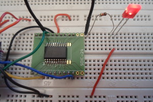
At this point the newly flashed firmware should start running: