TM1620 LED chip pin-out
14 June 2026After figuring out the Titan Microelectronics
TM1637 I also obtained other chips within the same general family and one of these is the TM1620.
Unlike the other chips the data-sheet for this one was only in Chinese or rather dubious machine translations but it was similar enough to the other data-sheets that I was able to work things out via a combination of familiarity and experimentation, and the purpose of this article is purely documentation of the specifics of the chip so that the information is at hand should it ever end up being selected for a project of mine.
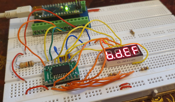
Compared to the TM1637 the polarity of the segment and grid pins is swapped with the former being anode connections and the latter cathode, in other words common-cathode, and two of the six grid pins can be reconfigured as extra segments.
There is also a third serial communications pin that that the TM1637 does not have which I think could be used as a chip-select to drive multiple units.
However as a trade-off the TM1620 does not have any button input capability.
TM1620 pin-out
Below is a reproduction of the pin-out from the data-sheet for the TM1620. Compared to the TM1637 the most notable difference is Pin 1 being ground rather than Vcc which is odd as almost all other pins that appear on both chips are either in the same place or the place next to it. Having the segment and grid pins in order and almost in one contiguous block is a nice touch. Pins 10 and 11 can be independently configured either as segments or grids.
| Serial | LED common | Ground | LED common | Ground | Seg 14 Grid 5 |
||||
| STB | CLK | DIO | Grid 1 | Grid 2 | Grid 3 | Grid 4 | |||
| 20 | 19 | 18 | 17 | 16 | 15 | 14 | 13 | 12 | 11 |
| 1 | 2 | 3 | 4 | 5 | 6 | 7 | 8 | 9 | 10 |
| Vcc | Seg 1 | Seg 2 | Seg 3 | Seg 4 | Seg 5 | Seg 6 | Seg 7 | Seg 8 | Seg 13 Grid 6 |
| LED segments (anode) | |||||||||
Command protocol
Whereas the TM1672 used a protocol that resembles I2C the TM1620 instead has a third control wire namedSTB which I think stands for Start Transmit Bit as this pin is used to signal the start and end of a command transmission.
Getting my existing TM1637 firmware working can be summed up as changing the start and stop to set this STB pin high/low instead of pulling/releasing clock/data, and removal of acknowledgement handling from byte transmission.
Note that in this case a restart is simply a stop followed by a start.
Since there is no situation with this chip where the clock/data line is read it should be possible to dispense with the pull-up resistors and instead drive the communication lines directly rather than using a pseudo open-drain setup.
Command set
Below is a condensed and simplified command set that shows the command combinations that are of practical use with the TM1720, with things such as test mode and the presumably-unimplemented key-scan reading excluded. Aside from some commands that other chip-sets have but are not implemented here, and conversely commands here that other chip-sets do not implement, this command set has been the same on allTM16xx data-sheets I have read so far.
| Bit 7 | Bit 6 | Bit 5 | Bit 4 | Bit 3 | Bit 2 | Bit 1 | Bit 0 | Function |
| 0 | 0 | Unused (set to zero) | 0 | 0 | Use Seg 13 & Seg 14 | |||
| 0 | 1 | Use Seg 13 & Grid 5 | ||||||
| 1 | 0 | Use Grid 6 & Grid 5 | ||||||
| 0 | 1 | Unused (set to zero) |
0 | 0 | 0 | 0 | Enable address auto-increment | |
| 1 | Disable address auto-increment | |||||||
| 1 | 0 | Unused (set to zero) |
0 | 0 | 0 | Set pulse width 1/16 | ||
| 0 | 0 | 1 | Set pulse width 2/16 | |||||
| 0 | 1 | 0 | Set pulse width 4/16 | |||||
| 0 | 1 | 1 | Set pulse width 10/16 | |||||
| 1 | 0 | 0 | Set pulse width 11/16 | |||||
| 1 | 0 | 1 | Set pulse width 12/16 | |||||
| 1 | 1 | 0 | Set pulse width 13/16 | |||||
| 1 | 1 | 1 | Set pulse width 14/16 | |||||
| 0 | One of above | Display off | ||||||
| 1 | Display on | |||||||
| 1 | 1 | Unused (set to zero) |
Address (0x0 – 0xb) |
Set display address | ||||
After issuing set display address which is byte value 0b1100xxxx the segment data is transmitted using the mapping in the next section.
LED data memory layout
Each byte pair corresponds to the segments that are lit on a grid and the grids are done in order, as summerised in the table below. This differs from the TM1637 which only has a single byte per grid, and the presence of unused bits is due to the same protocol being used on other chips within the family that have more segments available.
| First byte | Second byte | |||||||||||||||
| Bit 0 | Bit 1 | Bit 2 | Bit 3 | Bit 4 | Bit 5 | Bit 6 | Bit 7 | Bit 0 | Bit 1 | Bit 2 | Bit 3 | Bit 4 | Bit 5 | Bit 6 | Bit 7 | |
| Grid 1 (0x00) | Seg1 | Seg2 | Seg3 | Seg4 | Seg5 | Seg6 | Seg7 | Seg8 | Unused | Seg13 | Seg14 | Unused | ||||
| Grid 2 (0x02) | ||||||||||||||||
| Grid 3 (0x04) | ||||||||||||||||
| Grid 4 (0x06) | ||||||||||||||||
| Grid 5 (0x08) | ||||||||||||||||
| Grid 6 (0x0a) | ||||||||||||||||