KE04 breakout
30 December 2025Like many other electronic components ARM micro-controllers are no longer available in through-hole packages which is a pain since my preference is to use breadboard rather than custom PCBs, and have had a less than happy experience with off-the-shelf breakout boards. However difficulty in debugging means that I prefer not to use Microchip PIC chips these days as an alterative so needed to come up with a way to use ARM micro-controllers in prototyping circuits, and in looking for something that works for me decided to try the daughter-board design of breakout board with a few extra features that are commonly needed.
This board was sent for fabrication Christmas 2023 and a large stock of NXP MKE04Z8 micro-controllers which it is based around was also bought around the same time but circumstances meant it was only two years later that the breakout project was finished.
It was made a priority since these days what few electronics projects I do have time for are all on solder-less breadboard and I prefer not to always fall back to either Arduino nor PIC chips.
Circuit design & layout
Based around an NXPMKE04Z8 ARM Cortex-M0 the circuit design is essentially the same as the ARM I2C master built back in late-2019 but with many more pins broken out for external connectivity.
This earlier circuit was already very close to my requirements and being a known-good had the advantage of easy cross-checking rather than having to go back to primary technical documentation, with some design decisions simply being carried over.
Aside from the micro-controller it also had the following on-board:
- Flash header
- Anything other than a built-in programming header is a non-starter and using anything other than a standard connector easily turns into a world of pain. As explained later I have more or less given up on the MikroMatch-based system. All pins required for flashing are dedicated as this involves any complications that sharing functionality might bring.
- UART
- Even if only for debugging having an on-board USB-serial chip makes a whole load of hassle go away. In the past have had problems with 3v3 vs. 5v signalling and the extra space required compared to a pin header is well worth the trade-off.
- Indicator LED
- Needing some sort of indicator somewhere along the line is almost an inevitability so may as well include one on-board. Would have included more if there were the extra pins to spare.
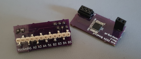
All eight of Port B’s pins are broken out including ones that are shared with on-board components because there are times when having a full eight-bits on a single port is useful, and shared ones could be freed up by leaving pads unpopulated. The list below are the pads that for the two boards assembled to date were left unoccupied.
- I2C pull-up resistors
- So many of my circuits use I2C that for convenience on-board pull-ups are included, but for now have been omitted as the most immediate projects are bit-banging. Quite likley they will be populated in the future.
- External oscillator
- The Kinetis technical documentation was not entitely clear what default clock speeds were and with the I2C master this was worked around by having an external oscillator of known value. This was carried over but only as a contingency as the boot-up default is now known to be 24MHz.
MikroMatch programming interface
Somewhere I have enough new-old stock to continue using my MikroMatch based flashing interface but for all intent and purposes I have virtually given up on this system. It was conceived and then open sourced because to me the price of ‘official’ connectors felt way over the top for what they were, but then the MikroMatch range which my system was based on was earmarked for discontinuation ane de-stocked by Farnell. Compared to the mini-ITC connectors it still feels so much more robust but in more recent circuit designs where space was not an issue I have gravitated towards using full-size 10-pin IDC connectors.
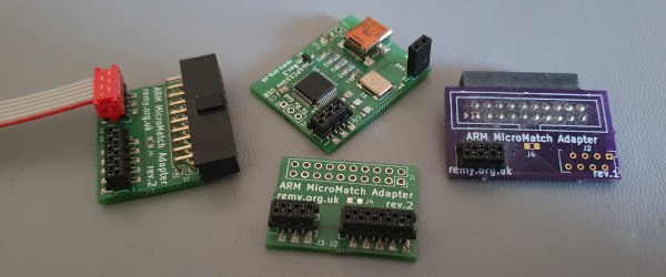
The real problem is a preference for built-in symbols and footprints complete with 3D models rather than importing component resources made with what is now a prehistoric version of KiCad, with the non-standard pinout being the ultimate show-stopper. While the 10-pin variant can use the standard JTAG symbol together with vendor-provided footprints so far it has yet to be used in a circuit and maybe it should stay that way, as although MikroMatch is a nice system it is not a long-term solution.
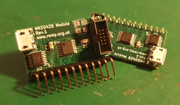
Daughter-board design
The circuit has been laid out like a mini daughter-board with just a single row of pins rather than the two typical of breakout boards in order to make it easier to install and remove as well as use up less breadboard space. Breakout boards tend to be very stiff to insert and remove which is a problem that also affects the Arduino, which in the past has been rather off-putting to use them with otherwise through-hole circuits. Having the insertion and removal force parallel to the board surface feels so much mow robust than action that feels like it might be bending the circuit board.
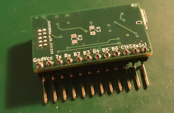
Undecided whether it is better for the pins to come out the front or back of the board but fow now marginally prefer them coming out front before bending down. Back in early-2000 I had previously made a simpler breakout board that used a single line of pins that were surface-mounted perpendicular to the bottom of the PCB but never took a liking to this approach. The labelling on the bottom was messed up so overall feel it best forgotten about which given the circumatances it practically was.
In hindsight it was probably rushed being one of five projects done before Covid-19 lockdowns really kicked off, and of these only one had any lasting success. Many circuits made back then were to have something to do rather than having any real longevity, and the ones I do look back at were on prototyping board rather than PCBs.
Remarks
I am fortunate to have a good stock of various ARM micro-controllers because some of them have since been de-facto discontinued such as the NXPLPC1112 in a SOIC package and others are now only available by the reel of thousands.
The NXP Kinetis KE series is also unusual for a Cortex-M0 chip in being able to run at 5 volts which for better or worse is my preferred operating power.
However various factors have resulted in so many of my electronics projects being put on hold for months and in this case years so getting it over the line was made a personal holiday priority.