CD4510B BCD counter
02 February 2021BCD (Binary Coded Decimal) is a system where four bits are used to represent the values 0 thru 9 instead of 0 thru 15, which has some conveniences when dealing with base-10 numbers but at the cost of leaving some bit-patterns unused. The Texas Instruments
CD4510B is a BCD chip I originally ordered by accident instead of the intended binary type CD4516B but later on decided to use it for a project where the counter wrapping around before it reached 0xf was a useful property.
However I decided to experiment with the chip in isolation prior to integrating it with this latter project.
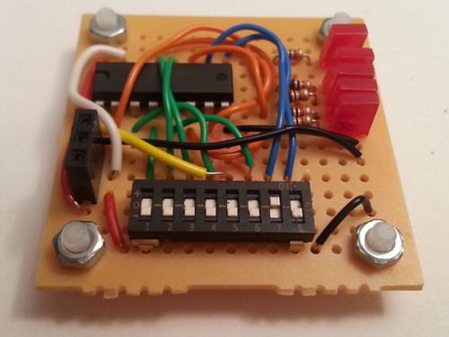
Building the test circuit
I am not sure if it is MulticompMC01006 or MDM 21-4570 but these 15-by-15 hole perf-boards are ones that I have stopped stocking in favour of the slightly larger Multicomp MC01007, and I thought that I had ran out of the smaller ones quite a while back.
However during a clear-out I found a few unused boards so decided to make use of them, since small test circuits such as this are one of the few things they are actually useful for.
The quality of the CD4510B data-sheet is pretty poor, looking like a scan of a multi-generational photocopy that makes it difficult to read, so I have reconstructed the pin-out in the table below using terminology which I find more representative of what the pins actually do.
| Vcc | Clock | Q3 | P3 | P2 | Q2 | Direction | Reset |
| 16 | 15 | 14 | 13 | 12 | 11 | 10 | 9 |
| CD4510B | |||||||
| 1 | 2 | 3 | 4 | 5 | 6 | 7 | 8 |
| Preset | Q4 | P4 | P1 | Enable | Q1 | Carry-out | Ground |
I don't know what theory is behind the pin assignment but it is a right pain compared to chips such as the SN74HC161N that group pins together on one side of the chip.
Maybe it was a thing with chips designed in the 1980s as the data-sheet looks like something from that era.
Details of the individual pins are given in the table below.
The preset and reset pins perform their function immediately upon being set high rather than on the next clock.
| Pin | Description |
| Clock | Increment/decrement on rising edge |
| P1 thru P4 | Preset values |
| Q1 thru Q4 | Counter output |
| Preset | If high, copies preset values to output |
| Enable | If high, increment/decrement disabled. |
| Carry-out | Low if wrap-around on next clock |
| Direction | Low for count-down; high for counting up |
The enable pin is listed as carry in within the data-sheet as it is intended for the carry bit when daisy-chaining chips together in order to represent multi-digit values, but in operation it amounts to a counter enable signal.
Sensitivity to bouncing
TheCD4510B is very sensitive to input bouncing, and even when using a simple resistor-capacitor debouncer certain combinations of output were always skipped, making me suspect the chip was faulty until I wired together a more fancy debouncing circuit that made use of a 555 timer setup as a Schmitt trigger.
Normally I would have from the outset used my active debouncer which I specially made for the task of experimenting with chips, but I did not have it with me so i had to make do with make-shift debouncing on solderless breadboard.