4-bit I/O Expander
19 September 2020It has been a long time since I wrote about I/O Expanders but the NXP
PCA9536 caught my eye since it is a small 4-bit one that may well be of use to me in the near future.
This article is intended as distilled-down notes on how to use the device, as I find that the way many data-sheets present information as needlessly over-complex.
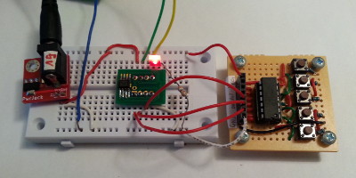
The PCA9536 itself is on the breakout adapter just left of the centre of the image on the white breadboard — the circuit to the right on the perf-board is a de-bouncing button array that does not leave things floating, which I used because I had no other buttons close at hand.
Pin-out
All packages the expander is available on are 8 pins and the pinning is the same on all of them. By default the I/O pins are configured as input and internally they have weak pull-up resisitors. The pin-out is summerised in the table below which is laid out to represent the top-down view of the chip.
| Vcc | SDA | SCL | I/O 3 |
| Pin 8 | Pin 7 | Pin 6 | Pin 5 |
| Pin 1 | Pin 2 | Pin 3 | Pin 4 |
| I/O 0 | I/O 1 | I/O 2 | Ground |
I2C interface
The device has a fixed address of0x82. When reading from or writing to the expander there is what the data-sheet calls the “command” byte although from an I2C transaction point of view it is really the Register 1 address.
There are four such registers and their purpose is summarised in the table below.
The device remembers which register was last read from, so for subsequent reads from the same register the register address can be omitted from a read transaction. Note that this only applies to reads and not writes, so I think it is simpler to always include the register address in all reads, as then things are less likley to go wrong.
| Regiser | Purpose | Lo value | Hi value |
| 0 | Input | Pin state | |
| 1 | Output | Output value | |
| 2 | Polarity | No change | Inverted |
| 3 | Pin configuration | Output | Input |
For each register the bits in the lower nibble correpond to the four pins and the upper nibble is not used.
The default power-up value for the polarity register is 0x00 (i.e. non-inverting) and for all other registers it is 0xff.
Test commands
For testing purposes I used myttyTxRx3.py serial communications script which is available from my Bitbucket repository, together with the Robot Electronics USB-ISS I2C master.
With these the following commands can be used to read the pin values:
./ttyTxRx3.py /dev/ttyACM0 1 55 83 0 1
Subsequent reads do not need to specify the register value:
./ttyTxRx3.py /dev/ttyACM0 1 53 83
If you want to write to Pin 3 the following commands will set it to output and then set the output value to high:
./ttyTxRx3.py /dev/ttyACM0 1 55 82 3 1 7 ./ttyTxRx3.py /dev/ttyACM0 1 55 82 1 1 8
Remarks
The lack of any address select pins is a bit of a pain but the device was clearly intended to be minimalist and this is not a show-stopper as there are I2C multiplexor chips out there. One big down-side of this expander is that it is not available as a through-hole 8-DIP but it seems that a lot of I/O Expanders are only available as surface-mount devices — so far thePCF8574 seems to be the only real show in town for simple through-hole 8-bit I/O expanders, but it is open-drain which for what I have in mind is not the right thing.